Part 1 – Static: To Linear, or Not to Linear, That Is the Question
Structural engineering has relied on linear analysis methods prescribed by design codes for decades. They are well established, efficient and familiar, but they have notable limitations. As designs become more complex, performance demands rise and computational power grows, the question arises: are traditional linear methods still adequate, or is it time to embrace nonlinear analysis?
This first part explores the advantages of nonlinear finite element analysis (NLFEA) over standard linear static methods, through a specific example: the shear failure of a reinforced concrete deep beam.
Balancing the pros and cons of NLFEA
NLFEA brings significant advantages for masonry and reinforced concrete, where nonlinear effects become critical after cracking and once the reinforcement yields. It simulates concrete crushing, nonlinear stress-strain relationships and bond-slip effects, which are essential for a realistic assessment of structural performance.
It also has its challenges: a strong grounding in structural analysis, careful modelling, informed assumptions and sensitivity analyses on material properties, boundary conditions and loads. Poorly built models can lead to significant errors, and the steep learning curve leads many engineers to prefer simpler linear methods. Faster computers, user-friendly interfaces and automation are now making NLFEA far more accessible.
Nonlinear modelling of R.C. and masonry members
Nonlinear behaviour can be modelled with lumped plasticity, concentrated at specific points such as the ends of beams and columns, or with distributed plasticity along the whole element, which is more accurate but computationally heavier. Both can use fibre sections; slabs and walls use layered shell elements, and three-dimensional components use solid elements. This article focuses on state-of-the-art 2D and 3D modelling, not yet widely adopted in practice but set to become more common.
Application example: shear failure of an R.C. deep beam
D-regions (“disturbed” or “discontinuity” regions) are areas where the stress distribution becomes nonlinear because of concentrated loads, support reactions or changes in cross-section. They are commonly analysed with the strut-and-tie model (STM) or with NLFEA.
The beam is 3600 mm long, 400 mm high and 200 mm wide, with a shear span of 743 mm (a shear span-to-height ratio of 1.86, which makes it a deep beam). It is reinforced with four 24 mm bars at the bottom, only two of which are fully anchored, two 24 mm bars at the top and 6 mm stirrups every 320 mm. The steel has fyk = 500 MPa and the concrete fck = 20 MPa; characteristic values are used without safety factors, to compare the analytical capacity with the FEM results.
The strut-and-tie solution
Following Eurocode 2, the strut capacity is 315 kN at the CCT node and 556 kN at the CCC node, and the tie capacity, given by the two anchored bars, is 452 kN. The beam shear capacity is governed by the compression failure of the CCT node: Vcd = 147 kN. Eurocode 2 reduces the strength of struts under transverse tension with a very simplified approach, and in biaxial and triaxial stress states its assumptions can be overly conservative.
The nonlinear FEM solution
The analysis uses a detailed 3D nonlinear model built with STKO and solved with OpenSees:
- Concrete: ASDConcrete3D, a plastic-damage model with the IMPL-EX integration scheme for fast, stable strain-softening simulations.
- Rebars: truss elements with fibre sections and the Steel02 model, embedded in the concrete with ASDEmbedded, developed by ASDEA Software.
- Bond-slip: STKO’s Beam-to-Solid Bar Slip condition, with the Pinching4 material.
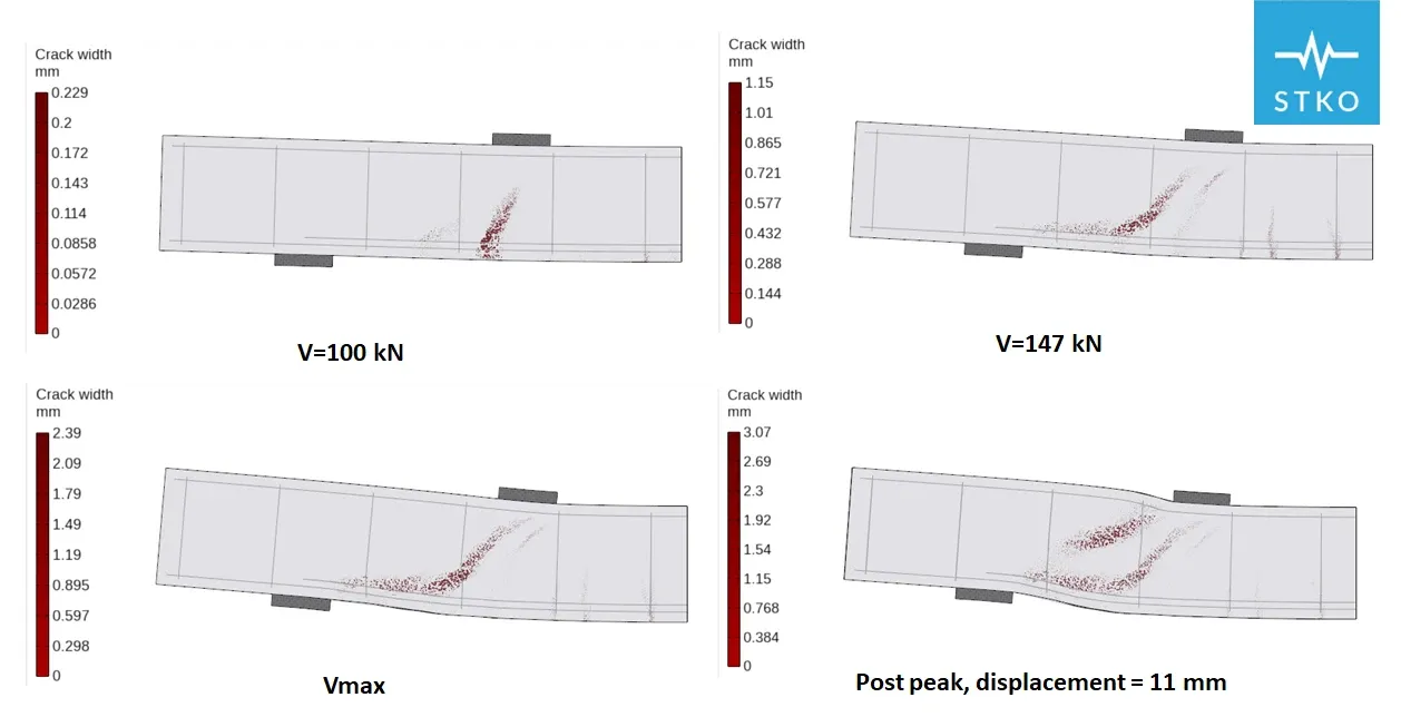
The predicted capacity is 200 kN, because the STM ignores the partially anchored bars and simplifies the 3D stress state of the concrete at the CCT node. Flexural cracks appear at 100 kN, shear cracks at 147 kN, and at the peak load the CCT node fails, with a maximum crack width of about 2.4 mm. The bars that are not fully anchored slip significantly, which limits the force they can transfer to the concrete: a phenomenon that simplified approaches such as the STM cannot capture.
The confinement effect
When a cracking beam is restrained by adjacent elements, its expansion generates an axial compressive force that increases its flexural and shear capacity. Design codes do not account for this effect, and linear analysis cannot assess it. With lateral confinement the beam reaches 243 kN, 22% more than without it, because the confinement reduces the transverse stresses in the compressive strut. Neglecting confinement in the assessment of beams, slabs and bridge decks can lead to conservative or inaccurate evaluations.
- Category
- Publications & White Papers
- Year
- 2024
- Sources
- Eurocode 2: Design of Concrete Structures (EN 1992-1-1:2004)
- fib Model Code 2010 and Model Code 2020
- Hendriks, M.A.N., Roosen, M.A. (2022), Guidelines for Nonlinear Finite Element Analysis of Concrete Structures, Rijkswaterstaat
- Author
- ASDEA Software
NLFEA offers substantial advantages over conventional linear methods wherever nonlinear behaviour, cracking and yielding occur. By modelling bond-slip, large deformations and stress redistribution, it gives a more precise and realistic assessment of structural behaviour, helping engineers optimise designs and improve safety in demanding applications such as earthquake-resistant structures, deep beams and masonry elements.
Despite its complexity, the need for specialised expertise and the computational resources it demands, NLFEA is becoming indispensable to modern structural engineering: as the discipline advances, it will be increasingly essential for design excellence and safety in complex, high-performance structures.
The predicted beam capacity is 200 kN, 36% higher than the capacity calculated with the strut-and-tie model.